Tiresias (the GPUkiller) 820-2915
Mounting instructions
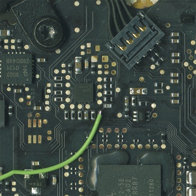
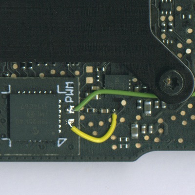
Remove R9704. The second wire connects to BKL_PWM (the top pin of where R9704 was).
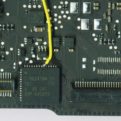
The first wire (yellow in our case) connects to WS_KBD23 (Test Point 1128).
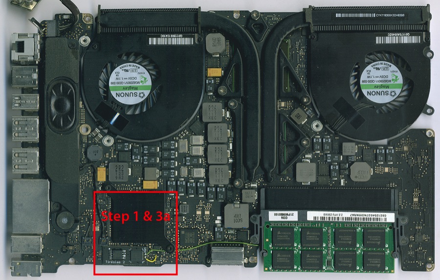
Step 1: Mount the Tiresias
The hole in the Tiresias fits snugly over the ROM chip. Solder all 8 connections from the Tiresias to the side of the ROM chip. Do not let too much solder flow down between the motherboard and the bottom of the Tiresias as that could cause a short circuit. In case you are not sure check for shorts between the adjacent pins on the ROM, there should not be any!
Use a soldering iron for the soldering, do not use hot air. If you are not proficient in soldering then do not attempt to install a Tiresias, rather get a professional to do it for you.
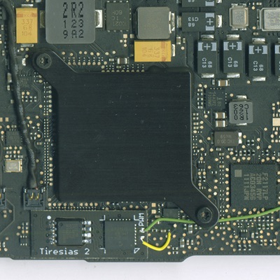
The Tiresias GPUkiller mounted over the ROM on the 820-2915.
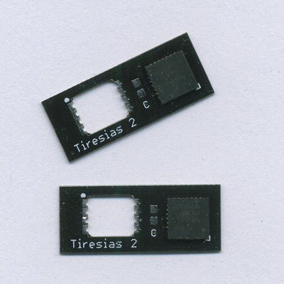
The Tiresias GPUkiller for the 820-2915.
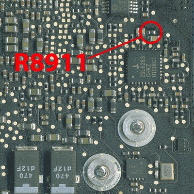
The position of R8911 which you have to remove on the 820-2915.
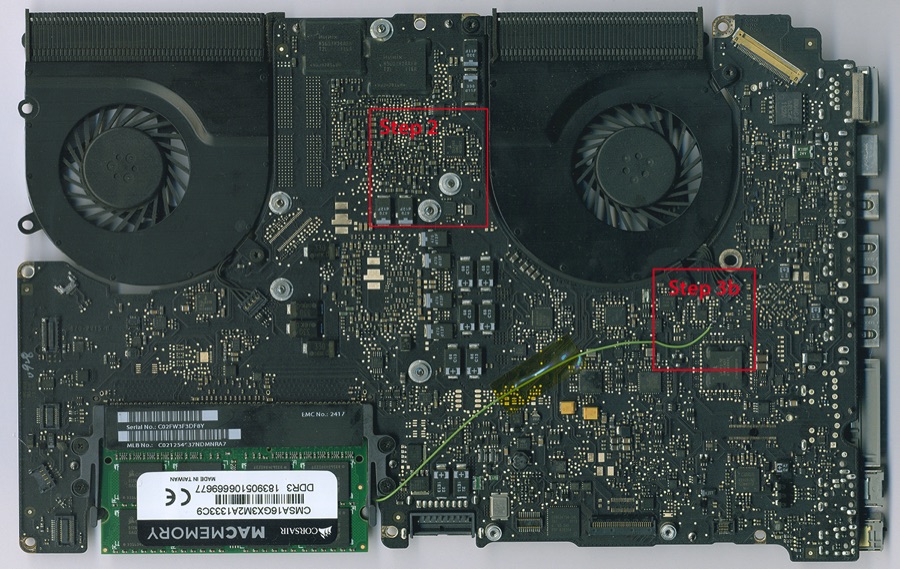
Step 2: (Important!) Turn off the (dead) GPU
Do not skip this step! One resistor has to be removed from the motherboard.
R8911 has to be removed to turn off the external AMD GPU.
This resistor has to be removed because the OS tries to talk to the GPU during boot. If it sees the GPU it might try to use it. And if it tries to speak to the GPU and the GPU gives strange answers (remember that it is dead...) then the Mac might crash when booting.
Step 3: Let the Tiresias do the brightness
Feel free to try the Mac after doing step 1 and 2 and BEFORE doing step 3. The Mac should go 'boing', give an image, and boot.
When you run High Sierra (or later...) then this step is NOT optional. Without it you can not control the brightness, and worse, the brightness will disappear altogether after system sleep. When you run any OS before High Sierra then mounting the two wires is optional but there is no problem if you do implement them.
If you want the Tiresias to handle the LCD backlight then you have to solder two wires from the Tiresias to the motherboard and remove one resistor.
The first wire (yellow in our pictures) connects to the unmarked pad on the Tiresias. The other end connects to WS_KBD23 on Test Point 1128. This wire is needed to be able to control the backlight with the F1/F2 keys after placing the green wire. If you don't need to control the backlight you can leave this wire out. (Thanks to Paul Daniels for pointing out the Test pad!)
The second wire (green in our pictures) is for the PWM signal that controls the brightness of the backlight. It connects to the PWM pad on the Tiresias. The other end connects to BKL_PK after sleep when running High Sierra or later.
It is important to install the wires and to remove R9704 together. If you remove R9704 without mounting the PWM wire you will have no backlight at all.

Alternative location for WS_KBD23 for connecting the yellow wire.
It is the 6th pin from the right.